
Hello. Did you have any problems with optics or light?
Hikari learning aims to be a light source that transmits various information under the theme of “optics”. The sources of information are public information on the Internet and some knowledge and experience of the author. This page describes “local and global coordinates”, which is essential knowledge of OpticStudio.
Conclusion
- Local coordinates are the center of coordinates an optical surface. Many local coordinates are located at the vertex of the surface, with some exceptions.
- Global coordinate is the coordinate centers that is as the reference for the entire optical system. OpticStudio allows you to any specify local coordinates as global coordinate.
Coordinate system of OpticStudio
This page describes “local coordinates of the optical surface, global coordinate of the optical system”. Although the coordinate system is important for setting the desired optical system, there are some parts that are difficult to understand.
I won’t go into detailed operation steps of the coordinate system, but I hope it helps you understand the meaning of the local and global coordinates used by OpticStudio.
Right-Handed Coordinate System
OpticStudio can handle 3D space in both sequential and non-sequential modes. Six parameters are required to determine the position information in 3D space. Position in the x, y, z and tilt about x-axis, y-axis, and z-axis.
Right-handed and left-handed systems define the positive direction of the reference xyz axis and the positive direction of rotation. According to Wikipedia , right-handed coordinates are used in many fields other than surveying.
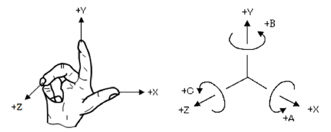
The right-handed system is like Figure 5-1 [1] with your right hand, with thumb = x-axis, index finger = y-axis, and middle finger = z-axis. The direction in which each finger facing is the plus direction of each axis. Also, for rotation around the center of each axis, the clockwise direction is positive rotation.
One of the reasons why it is difficult to define the coordinate system as expected is that “if the order of the modification of axes is different, the result of the coordinates will be different even if rotation values are same”. This is because the rotation of the coordinates is centered around the axes defined in the previous rotation. I guess the explanation may not be clear for you.
As an example, actually make a right-handed coordinate system by your hand. Please point the + z axis with the middle finger in front of you. Next, compare the results of rotation in the following order.
① Rotate +90 degrees about the x-axis (thumb). Next, rotate +90 degrees about the y-axis (index finger). The index finger points at an angle of 45 degrees forward and upward, like Fig 5-2 left picture.
② Rotate +90 degrees about the y-axis (index finger). Then rotate +90 degrees about the x-axis (thumb). The index finger points to the left as Fig 5-2right picture.

For definition of complex coordinate system requires spatial cognition capability and flexibility of the right arm joint to follow the axes operation.
Convention in otpical industry: The direction of rays travel is +z
There are several conventions in the long history of optical design. The following two may be typical ones for coordinate systems. Many past resources follow these conventions, so it’s a good idea to accept them for now.
① When drawing an optical system, we draw as rays travel from left to right.
② Take the positive direction of the z-axis in the direction of the rays.
By convention (2), when drawing an isometric view of a 3D layout with optical software, most software sets the ray (= + z-axis) toward the back of the screen by default. On the other hand, the default of mechanical CAD is set so that the + z axis faces toward the front of the screen (toward our side), so you need to be a little careful especially when communicating with mechanical engineers.
Sequential mode’s unique expression: Optical surface
I’d like to explain the coordinate system of OpticStudio. Sequential mode and non-sequential mode have a right-handed coordinate system and can use both local and global coordinates. But there are differences in how the optics are set. That is the idea of ”optical surface”.
As mentioned in the first article, sequential mode traces rays in the order of the user-defined faces. It’s not an optical component like a lens, but a surface. For example, one lens defines a “front side” and a “back side”, so two lines are needed in the lens data editor.
On the other hand, in non-sequential mode, the optical system is set by “object” including 3D shape with volume and surface shape without thickness. For example, one lens can be set in one line of the nonsequential component editor using an object type called “standard lens”.
Local coordinate
The local coordinates are the center of the face / the object itself. It may also be expressed as “local origin (reference point for defining the shape of the surface)”. Note that the position in local coordinates is not necessarily the vertex of the optical plane. For example, if the definition formula that determines the shape of a surface contains a decenter term, there will be a gap between the local origin of the optical surface and the optical surface.
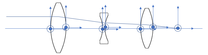
In sequential mode, the optical planes are defined one by one in local coordinates. In other words, the process of setting the optical system repeats the defining surface A → moving to the position of the local coordinates of surface B → defining surface B → moving the position of the local coordinates of surface C… If the axes of the optical system are straight, the movement of local coordinates between faces can only be handled by thickness.
If one lens is tilted or a reflection mirror is inserted, and the coordinate axes are not straight. The system requires parameters other than thickness to move from surface A to the local coordinates of surface B.
The means to enter this parameter is a special surface called Coordinate Break. This special surface is one of the hurdles to learning OpticStudio in terms of controlling local coordinates in sequential mode.
Global coordinate
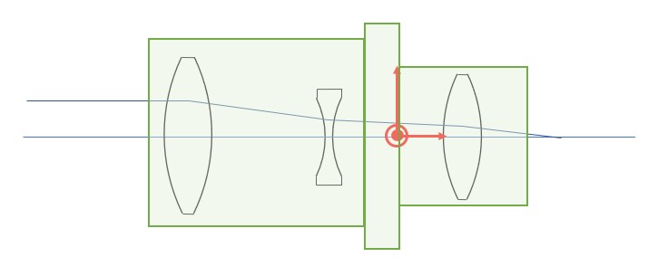
Global coordinate is the center of the entire system. As above, it is sometimes mentioned as the global origin. The global origin can be set anywhere. In some cases, the surface of the first lens of the optical system is set to global coordinates, and in some cases, when the construction of mechanical parts is determined as shown in Fig. 5-4, the center of the flange contact surface is set to global coordinates. If you agree with the mechanical engineer on the global coordinates, it will be easier to capture the optical design output as CAD data.
Summary
This page describes local coordinates and global coordinates of the optical surface and the right-handed system. Coordinate system would be a difficult point to use OpticStudio. If we understand how to control the coordinate system with cooridinate break surface and local/global system, we can define vary wide range of optics with OpticStudio.
<Reference>
[1] http://www.mt-kentei.jp/hint/hint_beg09.php

コメント